
MM Engines – 3200 Sport, 3200 Rally, & 3100 FI (Forced Induction) for the M50/M50tu/S50/S52/M52 (iron block)
Introduction
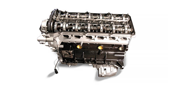
In 1991, BMW replaced the M20 with the M50 engine in the E34 525i. A year later the engine appeared in the E36 325i. This engine used the same bore centers as the earlier M20 but the outside of the block was cast differently to accommodate a DOHC (Double OverHead Cam) head. The engine was designed for low maintenance. This family of engines all use hydraulic lifter buckets and individual coil packs.
Then in 1993 the M50tu engine was introduced. The major technical update (tu) was VANOS (variable cam timing) that was added to the intake cam. The VANOS broadened the power output of the M50tu engine by advancing the intake cam by 25° just off idle to about 4400 RPM and then retarded the cam timing at higher RPM for top end performance. This single VANOS system was used up until 1999.
In 1996 the engine management system was changed from OBD I to OBD II. This was mandated by the US government through the Clean Air Act, declaring that all cars by ’96 have the newer On Board Diagnostics (OBD II). Most people that do engine swaps (mostly E30) or track their cars, convert to the earlier OBD I because it’s much easier to tune. OBD II engines, 1996 or later, have a timing reference sensor hole at the back of the block just under the starter, otherwise these cast iron blocks are the same as earlier blocks.
A rather hard to find aluminum M52/B28 block was made for the Z3 in 1997 and 1998. These aluminum blocks are 43 pounds lighter than the iron blocks and can be a big asset when it comes to handling. We have built some impressive MM 3000 & 3100 Rally/Race engines using these blocks for engine swaps.
All single VANOS heads up to ’96 are the same. On later OBD II heads, the cam reference sensor hole is a different size. Parts interchangeability within this family of engines is very good. For example, the S50/S52 engine used in the E36 USA M3 was basically a bored and stroked E36 325i engine with hotter cams. This is the one time BMW didn’t produce a special, more exotic engine for the M3. The rest of the world got the more complex, expensive, and higher output Euro S50/S52 engine. This makes the USA E36 M3 engine much more affordable for performance upgrades. For example, if we need to replace a cracked M3 head, we will usually try to find an equivalent year head from a 325i or 328i automatic because it’s generally going to be in better shape. A 325i/328i make less HP and for the most part people with automatics don’t drive hard.
Both of these factors reduce the intensity of the explosion in the combustion chamber and the heads don’t crack as often. The 325i head has weaker valve springs that tend to coil bind with the M3 intake cam so, springs and cams need to be changed to use the head on an M3, but the head itself is the same. In general, the E36 M3 and 328i/is models are better platforms to start out with for building a performance car. They have stronger drivetrain components, bigger brakes and better suspension than the 325i/is models. With that said, all these components will swap into a 325i/is. A Metric Mechanic engine in an E36 can really elevate the car’s power potential.
Metric Mechanic Engines
All rebuilt MM engines come delivered as Long Blocks – the Head(consisting of Camshaft/s with Cam Timing Set, Valves, Valve Springs, Valve Guides & Rocker Arm Assemblies) bolted onto the Short Block (consisting of the Block, Crankshaft, Rods, Pistons, Bearings and the Oil Pan). Accessories not included are the Intake/Exhaust Manifolds, Carburetor/Fuel Injection Systems, Alternator, Power Steering Pump, Air Conditioning Compressor, Harmonic Balancer, Clutch Assembly, Flywheel and Water Pump.
Understanding Torque & Horsepower
Torque and HP are the primary measurements used to describe the power output of an engine. Torque is expressed in ft/lbs and is a measure of the engine’s twisting force exerted on the crankshaft from combustion. Horsepower, which is derived from torque, is specifically a measure of how much torque the engine produces in one minute divided by 5252. Therefore, the HP formula is:
HP = Torque x RPM (Revolutions per Minute) ÷ 5252
Both HP and Torque are measured either at the Flywheel using an Engine Dynamometer or at the rear wheels using a Chassis Dyno.
How MM Engines Generate Power
Basic engine components are the block (pistons, rods, crankshaft) topped off with the head (cam/s, valves, valve train parts, etc).
The fill capacity (air and fuel mixture) of the Block’s cylinders, is what provides Torque while it’s the Head’s air intake that governs HP.
We use five techniques for modifying engine power! The first three occur in the block and the last two in the head.
- Lighter Reciprocating Mass (piston, piston pin & rod)
- Larger Displacement
- Increased Compression Ratio
- Improved Head Flow
- More Camming
1. Lighter Reciprocating Mass
Weight is the enemy of acceleration! For example, in a BMW E36 M3 engine, turning 7000 rpm, the piston starts from the top, accelerating to 100 mph by 75° after TDC, then starts to decelerate and stops at the bottom. The piston starts and stops 14,000 times a minute over a distance no wider than your fist, 3.5″ or 89.6mm. The reciprocating mass squares with RPM. For instance, from 2000 RPM’s to 4000 RPM’s, the RPMs are doubled but the engine recognizes a FOURFOLD increase in the Reciprocating Mass! If the RPM’s are doubled again to 8,000, the Reciprocating Mass is 16 times greater than at 2000 RPM’s. This is why we take Reciprocating Mass so seriously and strive to reduce it’s weight through lighter components. The Reciprocating Mass in our engines is 15% – 40% lighter than stock. This reduction spools up the crank quicker and increases the reliability of the engine – less reciprocating weight (piston and rod going up and down) to tear up the engine over time.
2. Larger Displacement
Larger displacement is accomplished by boring the block and increasing the crankshaft stroke. Displacement is a direct ratio of torque output meaning, a 10% increase in displacement results in a 10% increase in torque. Boring an engine is usually the most cost-effective way to increase displacement without increasing piston speed – which increases wear. Boring a cylinder out by 1mm, equals adding 2mm to the crankshaft stroke. At MM, we typically stroke an engine by installing a crankshaft with a longer stroke. In a few cases, we offset grind the crank.
3. Increased Compression Ratio
A simplified definition for Compression Ratio is: a measure of the entire Cylinder Volume plus the Combustion Chamber Volume divided by the Combustion Chamber Volume. Increasing the intensity of the combustion chamber explosion is accomplished by increasing the compression ratio. At Metric Mechanic, we normally increase the Compression Ratio by 1.5 to 2 points. For example, in a stock M3, CR is 10.5:1* and we take it up to 12.1 CR. *Note: BMW states that the stock M3 CR is 10.5:1 but when we CC it out, we get a real 9.5:1 and we take it up to what measures out at a real 11.1. Since we typically discover an approximate 8% variance increase in all BMW Compression Ratios, we used their calculating method in stating the M3 goes from 10.5:1 to 12.1. We don’t know but have suspected that they are calculating a carboning-up factor in the combustion chamber which would eventually increase the compression. For street driving, all our engines are designed to operate with 91 Octane. During Driver’s Schools, we recommend adding 1 gallon of 105 Octane Race Fuel per 3 to 4 gallons of 91 Octane Pump Gas. The objective here is to avoid detonation under extreme driving conditions.
4. Improved Head Flow
Porting the head allows for more fuel and air to flow past the intake valves at a given lift, for greater cylinder filling. Our cylinder head flow increases are as follows:
- M10 18% – 24% flow increase over the stock head
- M30 16% flow increase over the stock head
- M20 16% flow increase over stock the head
- S14/S38 16% – 26% flow increase over the stock head
- M42/M44 6% flow increase over the stock head*
- M50/S52 6% flow increase over the stock head*
- M54 6% flow increase over the stock head*
*Newer engines have an optimal port size of about 85% of the valve head and come from the factory machine ported, leaving less room for improvement.
Generally speaking, the cylinder filling and power gains will be about 1/2 the air flow increase of the ported head. For example, a 20% flow increase would equal a 10% increase in cylinder filling and power.
5. More Camming
We regard the camshaft as the crux of the entire engine. When designed right, it co-ordinates all other engine components to work optimally. Displacement, head flow, compression and driveability requirements, all factor into the camshaft profile design. Driveability requirements are determined by the owner’s driving style and how they use their BMW. A Metric Mechanic Sport Engine is designed for enthusiastic street driving whereas a Rally Engine covers that of course, but is also ready for Drivers Schools, Autocrossing and other driving events. They both have smooth idling qualities (with or without AC on) at 700 to 750 RPM, will work with the fuel injection idle circuit, and pass emissions testing anywhere in the world (in our experience so far). We meet these requirements by designing our camshafts to NOT exceed the overlap of the stock factory cams.
Our Sport and Rally Engines are build with a wide power band. Generally these engines make within 85% of their peak torque from 3000 to 3500 RPMs up to 6500 to 7000 RPM. This is done by running an intake lobe that is larger than the exhaust lobe. The Intake Lobe controls the upper RPM HP range whereas the Exhaust Lobe controls the low to mid-range torque. In 1988 we made a departure from the conventional practice of using identical intake and exhaust lobes and started designing the cam with a larger intake lobe than exhaust – a practice we continue to this day. Interestingly, BMW began this same strategy in 1995 with the E36 M3 Engine. Previously, the M50tu engine had Intake and Exhaust Lobes of 224° /9.0 Lift. In 1995 M3 S50 engine had a large Intake Lobe increase up to 252° / 10.3 Lift. The Exhaust Lobe was mildly increased to 234° at 9.7 Lift. Both the M50tu and the S50 Engine had 25° of Vanos (Variable Valve Timing) on the Intake Cam.
In Summary
These five areas (Reciprocating Mass, Displacement, Compression Ratio, Head Flow and Camming) are the keys to unlocking the power output of our Normally Aspirated or Boosted Engines.
The Effect of Driving Style on Reliability and Longevity
Driving Styles: Street vs. Tracking
Imagine cruising down a two lane road going to a Driver’s School event in a BMW E36 M3 with a 3.2 Liter Engine. After doing Driver’s Schools for a couple of years, you’ve moved up to the Advanced Level. Holding a speed of 60 mph at 2700 RPM, your foot is barely on the gas pedal and your fuel mileage indicator is showing 30+ miles per gallon. Your throttle plate, via the throttle cable, is barely open, severely limiting the amount of air intake. The engine is under light load now, and only needs to produce 10 HP and 19.5 ft. Lbs. of torque to cruise at 60 mph. Just ahead is a slower moving vehicle that you’d like to pass. So, your downshift from 5th to 3rd gear, put the pedal to the metal, and within 10 seconds you pass the car in front of you.
In that time, the intake throttle went wide open from 60 mph at 4500 RPMs to 80 mph at 6000 RPMs. The engine made 240 HP and 236 ft. lbs. of torque. Torque is indirectly related to the force, in pounds, pushing down on the piston top from the combustion chamber explosion. In the 10 second pass, the engine’s torque went from 19.5 ft. lbs. to 236 ft. lbs. and the combustion chamber explosion intensity increased by a factor of 12. Formula: 236 ÷ 19.5 = 12.1. The number of explosions increased by 2.2 times. Formula: 6000 ÷ 2700 = 2.2. If we take the intensity of the explosions x the increased number of explosions, we see that fuel consumption increased by 26.62 times. Formula: 12.1 x 2.2 = 26.2.
The increase in fuel consumption can also be figured out from HP. At 2000 RPMs, the engine was making 10HP. At 6000 RPMs, it was making 240 HP. If we divide 240 by 10, again we’ll see that the fuel consumption increased by 24 times – similar to the 26.62 result. So, for 10 seconds, your fuel economy went from 30 + mpg down to about 1.5 mpg.
At the Driver’s School Track
You finally arrive at the track for a 2 Day Driver’s School Event. For those of you who aren’t aware of what goes on at a Driver’s School, this is nothing like High School Driver’s Ed. At a Driver’s School, there are four levels of participation: Instructors, Advanced, Intermediate and Novice. Instructors and Advanced students drive solo due their experience level and their cars are well prepared; sticky tires, upgraded suspension and brakes. Advanced students and instructors are usually pushing their cars to within 90 to 95% of an SCCA (Sports Car Club of America) road racer. The main difference between a road race and a Driver’s School is that, before you can pass, the car in front of you must give a hand signal allowing the pass. Driving sessions are about 20 minutes long with 3 to 5 sessions a day over the 2 day event. So, for the weekend, you’ve now done 3 hours of hard Driver’s School time and burned up two tanks of gas and averaged about 7 miles per gallon. Going back to the 10 second pass, on the way to the track, the load on top of the piston is 12 times greater and the piston was exposed to 2.5 times the heat cycles as cruising down the road. Keeping this in mind, under these Driving School conditions, the life of a stock M3 engine would be about 50 – 75 hours barring breaking. Whereas a street driven M3 engine is good for 175,000 – 225,000 miles. In the end, high RPMs and high Loads, drastically shorten engine life.
Engine Wear
Oil Consumption – can be an indicator as to when an engine is worn out. Oil can enter the combustion chamber, causing the engine to “burn oil” in three different ways.
- Oil can get sucked up through the intake valve guide seals, by high intake manifold vacuum. BMW greatly reduced this problem in the mid ’80s with the advent of the Viton valve guide seals. Today, Metric Mechanic uses nothing but Viton valve guide seals. Bad valve guide seals can be diagnosed by running the engine to 5500 RPM in 3rd gear under full load, then closing the throttle plate by taking your foot off the gas for 3 – 5 seconds, then, push down on the gas peddle, and look for a cloud of blue smoke from the tail pipe. This indicates bad valve guide seals. Replacing the the valve guide seals and/or the valve guides usually leads to a valve job (recondition the valves by grinding them and the seats). Warning! Doing a valve job on a high mileage engine of a 125,000 to 150,000 miles can lead to a disaster. If your engine burns some oil, expect oil consumption to double after the valve job. Sealing up the valve to seat area, or increasing the head flow, can cause more combustion pressure to leak by the upper compression ring, increasing blow-by. Blow-by is explained in #3.
- Oil coming up from the crankcase pass the rings into the combustion Chamber. Most engines burn some oil this way, through out their life and this should be considered normal oil consumption for an engine. Most people today, don’t accept much in the way of oil consumption. BMW considers less than a quart in 450 miles as normal oil consumption. Things that cause oil consumption this way are; Tracking the Car, Hard Driving Style, Improper Break-In, Using incorrect oil during break-in (such as synthetic oil), excessive piston to cylinder wall clearance, improper honing, and an inappropriate ring selection.
- Blow-by is a more serious oil consumption problem and is usually the sign of a worn out engine. Here’s how Blow-By occurs in an engine. Late in the engine’s life, explosions in the combustion chamber cause 1) the compression ring to beat out it’s ring groove and 2) cylinder wall wear at the top of the compression ring’s travel. This action causes oil vapor in the crankcase to be forced up and out of the valve cover vent tube hole. The oil vapor then exits the engine through the breather hose, goes into the intake manifold and then is sucked into the engine where it burns the oil vapors. This is how Blow-By occurs in an engine.
Signs of Blow-by are:
- Oil Vapors spewing out of your vent tube.
- Oil build-up in your intake manifold.
- Oil turning black shortly after an oil change within 500 to 1000 miles.
- Increasingly higher levels of oil consumption
Higher mileage engines that take a noticeable down-turn in oil consumption, are usually experiencing blow-by. Once the oil consumption hits about 300 to 600 miles per quart (500 to 1000 kilometers per liter), the area around the upper compression ring is worn out. Now and engine will continue to run in a worn out condition but it will require lots of oil, plugs will want to foul out, engine smokes on start-up, gets harder to start, starts to misfire on cylinders and it’s a mess to keep running. It’s worn out and time for a rebuild.